EasyCookieInfo

Arduino-based Antenna Rotator Controller

 QST

Arduino Sketches

  •  myrotor_setup.ino    Software to run once at the beginning to setup the rotator

WiFi Magnetic Compass


20210118 200157

 Lido, IK5EKM, helping during tests


Caveat

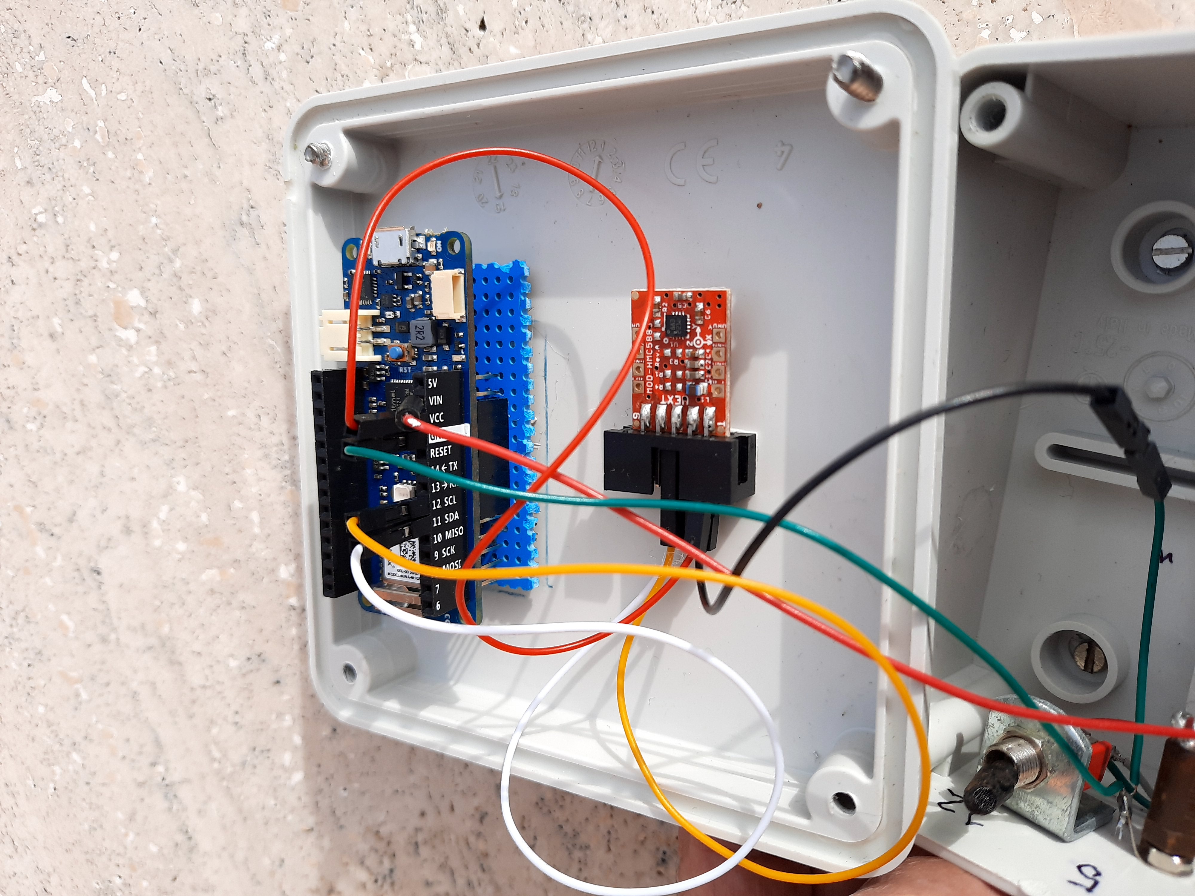
It seems that, since the article was submitted to QST, the breakout boards using the HMC5883L Honeywell magnetic sensor chip have become unavailable. On the other hand on the market there are several "clones" which share the same name but are not compatible with the libraries and the software used in this project. Using a clone in this project with the present software will give disappointing results.   

click here for information about distinguishing the "true"and the "clone chips.

It seems that the clone can be put to work satisfactorily but I do not have a direct experience with it. However I am willing to help and assist remotely those OMs who have got one and are not scared by experimenting a bit, adapting the software below. 


Article

Schematic Diagram

Fig1

Figures


Fig2  

Fig3 


   Fig5    Compass heading as displayed on the smartphone


foto1 cut

20210206 111530 2

Screenshot 2021 01 19 12.19.34

Screenshot 2021 02 03 11.51.35


 DSC 1707


Arduino Sketches and extra information


25/1/2022

Rotore per antenna TV Hirschmann Ro250

Acquistato nuovo imballato al mercatino di Viareggio

  • Aperta custodia del rotore con grande difficoltà a causa delle viti inox grippate sulla carcassa
  • Tolto il grasso secco dalla vite senza fine e ingrassata con grasso per cuscinetti rosso
  • Lubrificati ingranaggi con grasso PTFE


20200116 114208


20200116 114246


Problemi al controllore a causa dell'attrito tra il piattello  con i microswitch e la manopola di comando in Plexiglas. La manopola veniva trascinata in rotazione dal piattello a causa dell'attrito fra l'asse sopra il piattello e la boccola in plastica sulla manopola stessa. 


20200116 152307


20200116 152311


20200116 152332


Risolto alesando leggerissimamente la boccola della manopola con un tondino in legno (diametro 12) sui cui ho avvolto della carta vetrata


20200116 161630


WiFi Magnetic Compass 2


 WEB Compass


Under construction

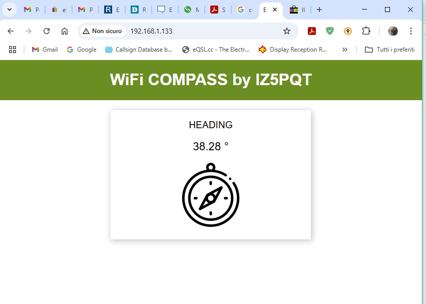
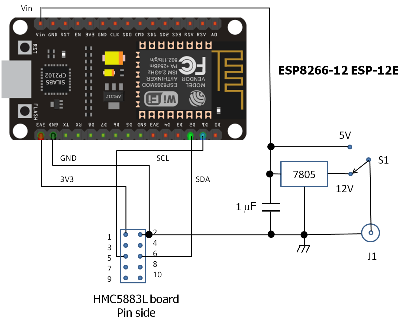
The Arduino MKR 1010 of the first compass version had its RF front-end broken, perhaps by an atmospheric discharge, so the WiFi no longer worked. Rather than replacing the board I investigated if the MKR 1010 could be replaced by something cheaper, and I came out with a solution based on the ESP8266 chip. At the same time I changed the Telnet readout with a more practical Web readout. The new compass still uses the the Olimex HMC 5883L board and no attempt was made to use the more recent chinese clones. 


Article for the MKR 1010

Schematic Diagram

ESP12 Compass

Figures


   Fig5    Compass heading as displayed on the smartphone


20210206 111530 2


 DSC 1707


Arduino Sketches and extra information


25/1/2022


DIY Yaesu FT-60 Programming Cable

  yaesu ft 60

The Yaesu FT-60 is a popular V/U HT introduced by Yaesu in 2005. Recently I purchased one used and I wanted to program the memories from my computer. However the special cable was a sort of mistery: I could not find a clear description of it, with most hams eventually resorting to a manufactured one. I found that making one myself was quite simple and the project is described below.


The project

The data transfer to and from the HT uses the 3.5 mm audio connector. Only two wires are used: ground and data signal. The data transfer to the PC occurs via a virtual serial port, and an USB to RS232 TTL adaptor takes care of level conversion. I used an FTDI FT232 board that can be purchased for few euros. The schematic diagram is shown below. The 10 k resistor is connected to the 3.3 V contact on the board. The power is supplied by the USB cable connected to the computer. On the board side the cable must terminate in a Mini (not Micro) USB plug. 

Immagine3

Schematic diagram of the programming cable.


The drivers for the board can be downloaded from the FTDI site. Similar boards using other chips can be used provided that the drivers are available for your operating system. Mine has been tested to work under Windows 10 using the CHIRP  free software.

NOTE

The original schematic did not have the diode and the resistor. Dale 2W0ODS informed me (thank you) that they are necessary to insure protection of the radio circuitry.  


The prototype

The prototype has been assembled without soldering: the few wires have been connected by simply twisting the leads together. To avoid tinkering with the mini jack I purchased a cable with the mini jack on one end and an USB A socket on the other. Then I plugged into it an USB A cable with the four wires stripped. I connected the DATA and GND wires to the pins of the FTDI adaptor. A USB Micro connector plugs into the adaptor. No power supply is needed, the power being supplied by the computer via the USB port. 


20230826 093941


20230826 093951


FT-60 Highlights:

  • Over 1000 Memory Channels w/Alpha-numeric Labels
  • Ten Memory Banks for Channel Allocation
  • High Power Output: 5 Watts
  • Long-life FNB-83 (7.2 V/1400 mAh) and Overnight Charger included
  • CTCSS and DCS Encode/Decode, with Split Tone and DCS Encode-only Capability
  • One-Touch NOAA Weather Access
  • NOAA Severe Weather Alert with Alert Scan
  • Nine DTMF Auto-Dialer Memories
  • Two Front Panel Programmable Keys
  • Convenient Access Key for Vertex Standard’s WIRES™ (Wide-coverage Internet Repeater Enhancement System)
  • RF Squelch (only passes signals exceeding programmed level)
  • Mono-band and Memory-only Operating Modes
  • Rugged Die-cast, Water-resistant Case Construction
  • Huge LCD Display
  • Transmit Time-Out Timer (TOT) and Automatic Power-Off (APO)
  • Automatic Repeater Shift (ARS)
  • YAESU’s exclusive ARTS™ (Auto-Range Transponder System) which "beeps" the user when you move out of communications range


HOME
© 1994-2023 Televideo.ws